A HYSDEL syntax was developed on C-language, and many symbols are similar. Structurally, a standard HYSDEL file comprises of two modes, namely INTERFACE and IMPLEMENTATION. Each of the sections is delimited by curly brackets e.g.
section {
...
}
and this holds for every kind of subsections as well. If one wants to add comments, this is simply done via C-like comments, i.e.
section {
...
/* this line is commented */
...
}
An example of the simplest HYSDEL file might look as follows
SYSTEM name {
/* example of HYSDEL file structure */
INTERFACE {
/* interface part serves as declaration of variables */
}
IMPLEMENTATION {
/* implementation part defines relations between declared variables */
}
}
Note that the file begins with SYSTEM string which is followed by the name. The name can be arbitrary, but it should be kept in mind that it usually points to a real object, therefore is recommended to use labels as e.g. tank, valve, pump, belt, etc. Other strings like INTERFACE and IMPLEMENTATION are obligatory. HYSDEL file can be created within any preferred text editor, however, the file should always have the suffix .hys, e.g. tank.hys. More importantly, it is recommended to use the name of the SYSTEM also as the file name, e.g. system called tank will be a file tank.hys etc. This becomes reasonable if there are more HYSDEL files in one directory and helps to identify the files easily. In the next content, the aim is to interpret new syntactical changes comparing to HYSDEL 2.0.5 version.
List of Language Changes
The list of topics of syntactical changes in HYSDEL \input{version.txt} is briefly summarized in the sequel, while the details will be explained in particular sections.
- INTERFACE section
- extensions of the INTERFACE section
- declaration of INPUT, STATE, OUTPUT variables in scalar/vectorized form
- declaration of subsystems
- IMPLEMENTATION section
- extensions of the IMPLEMENTATION section
- indexing
- FOR and nested FOR loops
- access to symbolic parameters
- operators and built-in functions
- AUX section
- CONTINUOUS section
- AUTOMATA section
- LINEAR section
- LOGIC section
- AD section
- DA section
- MUST section
- OUTPUT section
The INTERFACE section defines the main variables which appear for the given SYSTEM. More precisely, this section defines input, state and output variables distinguished by strings INPUT, STATE and OUTPUT. Moreover, additional variables which do not belong to these classes are supposed to be declared in the section called PARAMETER. A new feature of this version is that sometimes the block SYSTEM may contain other subsystems and this block should describe the overall behavior of the system. If this is the case, the MODULE section is to be present where subsystems are declared. This is the main change contrary to previous version.
Syntactical structure of the INTERFACE section has the following structure
INTERFACE { interface_item }
which comprises of curly brackets and interface_item. The interface_item may take only following forms
/* allowed INTERFACE items */
MODULE { /* module_item */ }
INPUT { /* input_item */ }
STATE { /* state_item */ }
OUTPUT { /* output_item */ }
PARAMETER { /* parameter_item */ }
where each item appears only once in this section. Each interface_item is separated at least with one space character and may be omitted, if it is not required. The order of each item can be arbitrary, it does not play a role for further processing.
Example: A structure of a standard HYSDEL file is shown here, where the INTERFACE items are separated by paragraphs, and curly brackets denote visible start- and end-points of each section.
SYSTEM name {
/* example of HYSDEL file */
INTERFACE {
/* declaration of variables, subsystems */
MODULE {
/* declaration subsystems */
...
}
INPUT {
/* declaration input variables */
...
}
STATE {
/* declaration state variables */
...
}
OUTPUT {
/* declaration output variables */
...
}
PARAMETER {
/* declaration of parameters */
...
}
}
IMPLEMENTATION {
/* relations between declared variables */
...
}
}
Related subsections of the INTERFACE part will be explained in more detailed in the sequel.
INPUT section
In the input section are declared input variables of the SYSTEM which can be of type REAL and BOOL. General syntax of the INPUT section remains the same, i.e.
INPUT { input_item }
where each new input_item is separated by at least one character space but the syntax of input_item differs for real and binary variables. The input_item for real variables takes the form of
REAL var [var_min, var_max];
where the string REAL, which denotes the type, is followed by var referring to name of the input variable, the strings [var_min, var_max] express the lower and upper bounds, and semicolon ";" denotes the end of the input_item. If there are more than one input variables, they are separated by commas ",", i.e.
REAL var1 [var_1_min, var_2_max], var2 [var_2min, var_2_max];
Example: Declaration of the scalar variable called input_flow, which is bounded between 0 and 10 m3/s will take the form
REAL input_flow [0, 10];
The input_item for Boolean variables takes the form of
BOOL var;
where the string BOOL, which denotes the type, is followed by var referring to name of the input variable, and semicolon ";" denotes the end of the input_item. Here the specification of bounds is not necessary because they are known but if even despite this one specifies the bounds on Boolean variables, HYSDEL will report an error. For more than one variables, separation by commas "," is required, i.e.
BOOL var1, var2, var3;
Example: Declaration of the scalar Boolean variables called switch and running will take the form
BOOL switch, running;
The main change comparing to previous version is that input variables may be defined as vectors, whereas the dimension of the input vector of real variables is nur and nub for binary variables. The corresponding syntax is as follows
REAL var(nur) [var_1_min, var_1_max;
var_2_min, var_2_max;
..., ...;
var_nur_min, var nur_max];
for variables of type REAL and
BOOL var(nub);
for Boolean variables. Note that according to expression in normal brackets "(" \; ")", which denotes the dimension of the vector, the lower and upper bounds are specified for each variable in this vector. These bounds are separated by commas "," and semicolon ";" denotes the end of row. If one declares variable in this way HYSDEL inherently assumes a column vector.
STATE section
STATE section declares state variables of the SYSTEM which can be of type REAL, and BOOL similarly as in the INPUT section. In general, the syntax of the STATE section is as follows
STATE { state_item }
where each new state_item is separated by at least one character space but the particular syntax of state_item differs for real and binary variables. The state_item for real variables takes the form of
REAL var [var_min, var_max];
where the string REAL, which denotes the type, is followed by var referring to name of the state variable, the strings [var_min, var_max] express the lower and upper bounds, and semicolon ";" denotes the end of the state_item. If there are more than one state variables, they are separated by commas ",", i.e.
REAL var1 [var_1_min, var_2_max], var2 [var_2_min, var_2_max];
Example Declaration of the scalar variables called position, which is bounded between 0 and 100 m, and speed (bounded from -10 to 10), will take the form
REAL position [0, 1000], speed [-10, 10];
The state_item for Boolean variables takes the form of
BOOL var;
where the string BOOL, which denotes the type, is followed by var referring to name of the Boolean state, and semicolon ";" denotes the end of the state_item. For more than one variables, separation by commas "," is required, i.e.
BOOL var1, var2, var3;
Example Declaration of the scalar Boolean state called is_open will take the form
BOOL is_open;
The main syntax difference, comparing to previous version, is that both REAL and BOOL variables may be defined as vectors. Denoting the dimension of the real state vector as nxr and dimension of Boolean state vector nxb allows one to define vectors as follows
REAL var(nxr) [var_1_min, var_1_max;
var_2_min, var_2_max;
..., ...;
var_nxr_min, var nxr_max];
for variables of type REAL and
BOOL var(nxb);
for Boolean variables. Note that according to expression in normal brackets "(", ")", which denotes the dimension of the vector, the lower and upper bounds are specified for each variable in this vector. These bounds are separated by semicolon ";" for each row. If one declares variable in this way HYSDEL inherently assumes a column vector.
Example We want to declare the state real vector xr where the first variable may vary in [-1, 1], and the second variable in in [0, 1]. Moreover, one Boolean state is present. The declaration of the STATE section will take the form
STATE {
REAL xr(2) [-1, 1; 0, 1];
BOOL xb;
}
which defines a real vector x_r in dimension 2 and scalar Boolean state xb.
OUTPUT section
In the OUTPUT section, output variables of the SYSTEM are to be declared. These variables can be of type REAL and BOOL, similarly as in the INPUT and STATE section. In general, the syntax of the OUTPUT section is as follows
OUTPUT { output_item }
where each new output_item is separated by at least one character space and differs for real and binary variables. The output_item for real variables takes the form of
REAL var;
where the string REAL, which denotes the type, is followed by var referring to name of the output variable. More variables are delimited by commas "," as in the INPUT and STATE section.
Note that in the OUTPUT section no bounds are specified. It is because the output variable is always considered as an affine function of states and inputs, thus their bounds are automatically inferred.
Example Declaration of the scalar output variables called y1 and y2 will be as follows
REAL y1, y2;
where no bounds are specified.
The output_item for Boolean variables takes the form of
BOOL var;
where the string BOOL, which denotes the type, is followed by var referring to name of the Boolean output, and semicolon ";" denotes the end of the output_item. If there are more output variables, they are delimited by commas ",".
Example Declaration of the scalar Boolean output variables d1, d2, and d3 will take the form
BOOL d1, d2, d3;
which is the same as in HYSDEL 2.0.5.
Comparing to previous version, output variables may be defined as vectors. Denoting the dimension of the real output vector as nyr and dimension of Boolean output vector nyb allows one to define
REAL var(nyr);
for variables of type REAL and
BOOL var(nub);
for Boolean variables with nub specifying the dimension of the column vector.
Example We want to declare the output real vector yr, the second output real vector q and one binary vector outputs d
OUTPUT {
REAL yr(2), q(2);
BOOL d(3);
}
PARAMETER section
The PARAMETER section declares variables which will be treated as constants through whole HYSDEL file structure. In this case the syntax of the PARAMETER section is as follows
PARAMETER { parameter_item }
where each parameter_item may take one of the following forms
- declaration of constants type var = value;
- declaration of constant column vectors with dimension n (the dimension does not have to be present for constants) type var = [value_1; value_2; ..., value_n];
- declaration of constant matrices with dimensions n times m (the dimension does not have to be present for constants) type var = [value_11, value_12, ..., value_1m;
- value_21, value_22, ..., value_2m;
- ..., ..., ..., ...;
- value_n1, value_n2, ..., value_nm];
type var1 = value1; type var2 = value2;
type var3 = value3;
Notations in vector and matrix description remain the same as in INPUT, STATE and OUTPUT section. That is, each element of the row is delimited with comma "," and the row ends with semicolon ";" .
Example We want to declare constants a=1 as Boolean variable, b=[-1, 0.5, -7.3]^T and D = [ -1, 0, 0.23; 0.12, -0.78, 2.1 ] as real variables. This can be done as follows
PARAMETER {
BOOL a = 1; REAL b = [-1; 0.5; -7.3];
REAL D = [-1, 0, 0.23; 0.12, -0.78, 2.1];
}
Moreover, PARAMETER section also allows symbolic parameters of type REAL, assuming that their values will be specified later. If the parameter is symbolic, its declaration reads
PARAMETER {
type var; /* symbolic scalar */
type var(n); /* symbolic vector */
type var(n,m); /* symbolic matrix */
}
where the string type is either REAL or BOOL and the variable var can be scalar, vector with n rows, or matrix with dimensions n and m.
Note that dimension of symbolic vectors/matrices, i.e. n, m must not be symbolic parameters.
However, the presence of symbolic variables leads to bad conditioning of the resulting MLD model and therefore it is always required to assign particular values to symbolical expressions before compilation.
If there is a strong need to keep symbolic parameter is MLD models, it is recommended to specify lower and upper bounds on each declared symbolic parameter. The syntax in this case is similar to INPUT, STATE and OUTPUT section,
REAL var [var_min, var_max];
whereas the declared variable var can be only scalar. If there are more symbolic values, they are separated by commas ",".
Note that huge number of symbolic parameters may prolong the compilation time as the number of involved operations is sensitive on symbolic expressions. Furthermore, symbolic expressions have to be replaced with exact values, if the HYSDEL model is going to be further processed.
HYSDEL language supports several numerical expressions, here is example of allowed formats
REAL a = 1.101;
REAL tol = 1e-3;
REAL eps = 0.5E-4;
REAL Na = 6.0221415e+23;
where the decimal number is separated with dot "." and the decadic power is corresponds to sign "e" or "E". Additionally, HYSDEL language has a predeclared variable, to which it suffices to refer with a given string. Precisely,
pi; /* pi = 3.141592653 */
and their value can be overridden by the user.
Example We want to declare boolean constant vector h=[1, 0, 1]^T, real matrix A = [pi, -0.05x10^2; -0.8, 12x10^{-3}], symbolic vector v, and symbolic value p which may vary between [-0.5, 1.8]. The HYSDEL syntax will take the form
PARAMETER {
BOOL h = [1; 0; 1]; /* constant vector */
REAL A = [pi, -0.05e2; -0.8, 12E-3]; /* constant matrix */
REAL v(2); /* symbolic vector, will be replaced with real
value before compilation */
REAL p [-0.5, 1.8]; /* symbolic parameter, which remains
symbolic also after compilation * /
}
IMPLEMENTATION section
Relations between variables are determined in the IMPLEMENTATION section. According to type of variables, this section is further partitioned into subsections, which remain the same as in previous version. Syntactical structure of the IMPLEMENTATION section has the following form
IMPLEMENTATION { implementation_item }
which comprises of curly brackets and implementation_item. The implementation_item may take only following forms
AUX { /* aux_item */ }
CONTINUOUS { /* continuous_item */ }
AUTOMATA { /* automata_item */ }
LINEAR { /* linear_item */ }
LOGIC { /* logic_item */ }
AD { /* ad_item */ }
DA { /* da_item */ }
MUST { /* must_item */ }
OUTPUT { /* output_item */ }
where each item appears only once in this section. Each implementation_item is separated at least with one space character and may be omitted, if it is not required. The order of each item can be arbitrary, it does not play a role for further processing.
Note that OUTPUT section is also present as in the INTERFACE part but here it has different syntax and semantics.
New changes in the IMPLEMETATION section affect the syntax of each subsection and the common features are listed as follows:
- indexing
- FOR and nested FOR loops
- operators and built-in functions
Example A structure of the standard HYSDEL file is given next where the meaning of each subsection of the IMPLEMENTATION part is briefly explained
SYSTEM name {
INTERFACE {
/* declaration of variables, subsystems */
}
IMPLEMENTATION {
/* relations between declared variables */
AUX {
/* declaration of auxiliary variables, needed for
calculations in the IMPLEMENTATION section */
}
CONTINUOUS {
/* state update equation for variables of type REAL */
}
AUTOMATA {
/* state update equation for variables of type BOOL */
}
LINEAR {
/* linear relations between variables of type REAL */
}
LOGIC {
/* logical relations between variables of type BOOL */
}
AD {
/* analog-digital block, specifying relations between
variables of type REAL to BOOL */
}
DA {
/* digital-analog block, specifying relations between
variables of type BOOL to REAL */
}
MUST {
/* specification of input/state/output constraints */
}
OUTPUT {
/* selection of output variables which can be of type
REAL or BOOL) */
}
}
}
Indexing
Introducing vectors and matrices induced the extension of the HYSDEL language to use indexed access to internal variables. The syntax is different for vectors and matrices since it depends on the dimension of the variable. Access to vectorized variables has the following syntax
new_var = var(ind);
where new_var denotes the name of the auxiliary variable (must be defined in AUX section), var is the name of the internal variable and ind is a vector of indices, referring to position of given elements from a vector. Indexing is based on a MATLAB syntax, where the argument ind must contain only [1, 2, ... ] valued elements and its dimension is less or equal to dimension of the variable var. Syntax of the ind vector can be one of the following:
- increasing/decreasing sequence ind_start:increment:ind_end
- increasing by one sequence ind_start:ind_end
- particular positions [pos_1, pos_2, ..., pos_n]
- nested indices ind(sub_ind)
Example In the parameter section were defined two variables. The first variable is a constant vector h = [-0.5, 3, 1, pi, 0]^T and the second variable is a symbolical expression g, bounded between [-1, 1], [-2, 2], and [-3, 3]. We want to assign new variables z and v for particular elements of these vectors. Examples are:
- increasing sequence, e.g. z = [-0.5, 1, 0]^T z = h(1:2:5);
- decreasing sequence, e.g. v = [g_3, g_2]^T v = g(3:-1:2);
- increasing by one, e.g. z = [1, pi, 0]^T z = h(3:5);
- particular positions, e.g. v = [g_1, g_3]^T v = g([1,3]);
- nested indexing, e.g. z = [3, pi]^T, k = [2, 3, 4] z = h(k([1, 3]));
Indexing of matrices is similar, however, in this case two indices are required. The indexed syntax takes the following form
new_var = var(ind_row,ind_col);
where new_var denotes the name of the auxiliary variable (must be defined in AUX section), var is the name of the internal variable, ind_row is a vector of indices referring to rows, and ind_col is a vector of indices referring to columns.
Note that indexing is based on a MATLAB syntax, where the argument ind must contain only [1, 2, ... ] valued elements and its dimension is less or equal to dimension of the variable var.
Syntax of the items ind_row, ind_col is the same as for vectors the item ind.
Example In the parameter section a constant matrix is defined `A = [ 0, -5, -0.8, 1;
-2, 0.3, 0.6,-1.2; 0.5, 0.1, -3.2, -1]`
We may extract values from matrix A to form new variable B as follows
- increasing sequence, e.g. B = [ 0, -5; -2, 0.3] B = A(1:2,1:2);
- decreasing sequence, e.g. `B = [0.5, 0.1, -3.2, -1;
B = A(3:-1:1,1:4);
- particular positions, e.g. B = [0, 0.3, -3.2]^T B = A(1:3,[1, 2, 3]);
- nested indexing, e.g. B = [0.6, -1.2]^T, `i_row =
B = h(i_row,i_col(3:4));
where the variables i_row and i_col have to be declared first.
FOR loops
FOR loops are another important feature this HYSDEL version. To create a repeated expression, one has to first define an iteration counter in the AUX section according to syntax
AUX {
INDEX iter;
}
where the prefix INDEX denotes the class, and iter is the name of the iteration variable. If there are more iteration variables required, the additional variables are separated by commas ",", i.e.
AUX {
INDEX iter1, iter2, iter3;
}
As the iteration variable is declared, the FOR syntax takes the form of
FOR ( iter = ind ) { repeated_expr }
where the string FOR is followed by expression in normal brackets "(", ")" and expression in curly brackets "{", "}". The expression in normal brackets is characterized by assignment `iter = ind where the iteration variable iter` incrementally follows the set defined by variable ind and this variable takes one of the form shown in section HysdelLanguage#Indexing. The expression in curly brackets named repeated_expr is recursively evaluated for each value of iterator iter and can take the form of
aux_item
continuous_item
automata_item
linear_item
logic_item
ad_item
da_item
must_item
output_item
depending in which section the FOR loop lies. This allows to use the FOR loop within the whole IMPLEMENTATION section.
Example Suppose, that it is required to repeat ad_item in the AD section for each binary variable d_i if state x_{ri} >= 0, i=1, 2, 3, ... The iteration index, as well as auxiliary Boolean variable $d$ has to defined first,
AUX {
INDEX i;
BOOL d(3);
}
and they can be consequently used in the AD section as follows
AD {
FOR (i=1:3) { d(i) = xr(i) >= 0; }
}
HYSDEL 3.0 supports also nested loops. In this case the syntax remains the same, but the repeated_expr has now the structure of
FOR ( iter = ind ) { repeated_expr }
which does not differ from the syntax outlined above.
Example Suppose that we want to code a matrix multiplication for state update equation. Assuming that vectors x, u are already declared, we also declare constant matrices in the INTERFACE section
PARAMETER {
REAL A = [1, 0.5; 0.2, 0.9];
REAL B = [1; 0];
}
Secondly, we define iteration counters in IMPLEMENTATION section
AUX {
INDEX i,j;
}
and then use the nested loop syntax as follows
CONTINUOUS {
FOR (i=1:2) {
x(i) = 0;
FOR (j=1:2) { x(i) = A(i,j)*x(j) + x(i); }
x(i) = x(i) + B(i)*u;
}
}
FOR loops allow also to more complicated expressions. For instance, indexing in a power sequence 2^i where i=1,...,5. Assume that for given vector h it is required to assign a real variable z according to power sequence indexing. In HYSDEL it can be written as follows
FOR (i=1:5) { z(i) = h(2^i); }
where the variables i, z, and h were previously declared.
Accessing Symbolic Parameters
Symbolic parameters allow more flexibility when creating MLD models. They are declared in the PARAMETER section and in the MODULE section independently, but access is the same. In general, the access is like in Matlab structures. For a standard HYSDEL slave file (which does not have any MODULE section) the syntax takes the common form
SYSTEM name {
INTERFACE {
/* other parts are omitted */
...
PARAMETER {
type var;
type var(n);
type var(n,m);
type var [var_min, var_max];
}
}
IMPLEMENTATION {
/* other parts are omitted */
}
}
and after compilation the symbolic variables are stored in a structure called S under fields params, i.e.
S.params.var
If the HYSDEL file contains a MODULE section it is built from subsystems declared in this section. The parameters of the subsystems can be now replaced with concrete values, using the following syntax
SYSTEM master {
INTERFACE {
/* other parts are omitted */
MODULE {
subsystem name1, name2;
}
PARAMETER {
name1.var = value1;
name2.var = value2;
}
}
IMPLEMENTATION {
/* other parts are omitted */
}
}
In the remaining IMPLEMENTATION section the symbolical values will be automatically replaced with numerical values.
Example Suppose that a master file tank is created by two subsystems valveA and valveB. Both of the slave file contains symbolical parameters height and width as in this example for valveA
SYSTEM valveA {
INTERFACE {
/* some parts are omitted */
...
PARAMETER {
REAL width, height;
}
}
}
The exact values can be set in the master file as follows
SYSTEM tank {
INTERFACE {
/* some parts are omitted */
...
MODULE {
valves valveA, valveB;
}
PARAMETER {
valveA.width = 0.15;
valveA.height = 0.23;
valveB.width = 0.2;
valveB.height = 0.35;
}
}
}
Builtin functions
| Relation | Operator | HYSDEL representation |
| addition | + | + |
| subtraction | - | - |
| multiplication | . | * |
| elementwise multiplication | . | .* |
| division | / | / |
| elementwise division | / | ./ |
| absolute value | |a| | abs(a) |
| a | to the power of ba | ba.^b |
| e^b | exp(b) | exp(b) |
| square root | sqrt(a) | sqrt(a) |
| common logarithm (with base 10) | log(a) | log10(a) |
| natural logarithm (with base | e)ln(a) | log(a) |
| binary logarithm (with base 2 ) | log_2(a) | log2(a) |
| cosine | cos(a) | cos(a) |
| sine | sin(a) | sin(a) |
| tangent | tan(a) | tan(a) |
| Relation | Operator | HYSDEL representation |
| matrix/vector addition | + | + |
| matrix/vector subtraction | - | - |
| matrix/vector multiplication | . | * |
| matrix power | A | bA^b |
| vector sum | sum(a) | sum(a) |
| 1-norm of a vector | sum(|a|) | norm_1(a) |
| infinity-norm of a vector | max(a) | norm_inf(a) |
| Relation | Operator | HYSDEL representation |
| or | or | or |
| and | and | & |
| one way implication | -> | -> |
| one way implication | <- | <- |
| equivalence | <-> | <-> |
| negation | not | ~ |
| Function | HYSDEL representation |
| true if all elements of a vector are nonzero | all(a) |
| true if any element of a vector is nonzero | any(a) |
AUX section
In the AUX section one has to declare auxiliary variables needed for derivations of further relations in the IMPLEMENTATION section. The declaration of these variables follows with specifying the type of the variable (REAL, BOOL or INDEX) and defining the name, e.g.
type var;
where the string type can be REAL, BOOL or INDEX and it is followed by a variable var. If there are more variables, they are delimited by commas ",".
Example Suppose that in the AUX section we have to declare two iterators i, j, two real vectors z, v and Boolean variable d. The AUX syntax takes the following form
AUX {
INDEX i,j; /* iteration counters */
REAL z(3),v(2); /* auxiliary REAL vectors */
BOOL d(5); /* auxiliary BOOL vector */
}
Contrary to INTERFACE section, here lower and upper bounds on the variables are not given. The values are automatically calculated from variables declared in the INTERFACE section since AUX variables are affine functions of these variables. Moreover, no constants, as well as no parameters are here declared.
CONTINUOUS section
In the CONTINUOUS section the state update equations for variables of type REAL are to be defined. The general syntax is given as
CONTINUOUS { continuous_item }
where the continuous_item may be inside a FOR loop and takes the form
var = affine_expr;
The variable var corresponds to the state variable declared in the section STATE and it can be scalar or vectorized expression. The affine_expr is an affine function of parameters, inputs, states and auxiliary variables, which have been previously declared.
Note that only variables of type REAL, declared in STATE section can be assigned here.
Example Suppose that the state update equation is driven by x(k+1) = Ax(k) + Bu(k) + f equation where the matrices A, B, f are constant parameters, x is state, u is input. This can be written in HYSDEL language as short vectorized form, i.e.
CONTINUOUS {
x = A*x + B*u + f;
}
AUTOMATA section
The AUTOMATA section describes the state transition equations for variables of type BOOL. The general syntax takes the form
AUTOMATA { automata_item }
where the automata_item may be inside a FOR loop and is built by
var = Boolean_expr;
The variable var corresponds to the Boolean variable defined in the section STATE and it can be scalar or vectorized expression. The Boolean_expr is a combination of Boolean inputs, Boolean states, and auxiliary Boolean variables with operators reported in HysdelLanguage#Builtinfunctions.
Note that only variables of type BOOL, declared in STATE section can be assigned here.
Example Suppose that the Boolean state update is driven by following relations x_2(k+1) = u_1(k) or ( u_2(k) and not x_1(k) ). Related HYSDEL syntax will take the form of
AUTOMATA {
xb(2) = ub(1) | (ub(2) & ~xb(1));
}
LINEAR section
In the LINEAR section it is allowed to define additional variables, which are build by affine expressions of states, inputs, parameters and auxiliary variables of type REAL. In general, the structure of the LINEAR section is given by
LINEAR { linear_item }
where the 1inear_item may be inside a FOR loop and takes the form of
var = affine_expr;
The variable var is of type REAL and was previously declared in the AUX section. The `affine_expr1 is an affine function of parameters, inputs, states and auxiliary variables of type REAL, which have been previously declared.
Example Consider that it is suitable to define an auxiliary continuous variable g = -0.5x_1 + 3 which is an affine function of the state. The variable is firstly declared in the AUX section,
AUX {
REAL g;
}
and consequently, the expression in LINEAR section takes the form
LINEAR {
g = -0.5*x(1) + 3;
}
Furthermore, the LINEAR section is devoted to determine relations between subsystems and applies only if there is MODULE section present. More precisely, the syntax is given by
var = affine_expr;
where the variable var access the internal input or output variable of type REAL of the declared subsystem. The affine_expr is an affine function of internal inputs or output variables of type REAL of the declared subsystems. More detailed view for merging of subsystems will be given in special section.
Note that LINEAR section serves also for declaration of interconnection between subsystems (if they are declared in MODULE section).
LOGIC section
LOGIC section allows to define additional relations between variables of type BOOL which might simplify the overall notations. In general the syntax is given by
LOGIC { logic_item }
where the logic_item may be inside a FOR loop and is built by
var = Boolean_expr;
The variable var corresponds to the Boolean variable defined in the section AUX and it can be scalar or vectorized expression. The Boolean_expr is a combination of Boolean inputs, Boolean states, and auxiliary Boolean variables with operators reported in HysdelLanguage#Builtinfunctions.
Example Suppose that we want to introduce the Boolean variable d = x_1 and ( not x_2 or not x_3), which is a function of Boolean states. We proceed first with variable declaration in AUX section
AUX {
BOOL d;
}
and follow with LOGIC section
LOGIC {
d = x(1) & (~x(2) | ~x(3));
}
AD section
AD section is used to express the relations between variables of type REAL to Boolean variables only with help of logical operator equivalence. Here, the equivalence operator <-> is replaced with = operator and the syntax is given as
AD { ad_item }
where the ad_item might be inside a FOR loop and it can be one of the following
var = affine_expr >= real_num;
var = affine_expr <= real_num;
The variable var is of type BOOL and has to be declared in the AUX section. The affine_expr is a function of states, inputs, parameters and auxiliary variables of type REAL. Operator >= denotes the greater or equal inequality and operator <= is less or equal inequality. Expression real_num is a real valued number.
Example Suppose that we want to assign to a Boolean variable d value 1 if certain inequality is satisfied, otherwise it will be 0. HYSDEL allows to model this behavior using AD syntax
AUX {
BOOL d(3);
}
AD {
d(1) = x(1) + 2*u(2) >= 0;
d(2) = 0.5*x(2) - 3*x(3) <= 0;
d(3) = x(1) >= 1.2;
Previous version required bounds on auxiliary variables var in the form of
var = affine_expr >= real_num [min, max, eps];
var = affine_expr <= real_num [min, max, eps];
but this syntax is obsolete and related bounds calculation are now obtained automatically. If the bounds will be provided anyway, HYSDEL will raise a warning.
Note that AD section does not use curly brackets "{", "}" to assign the auxiliary variable.
DA section
The DA section defines continuous variables according to if-then-else conditions. HYSDEL language supports the following syntax
DA { da_item }
where the da_item might be inside a FOR loop or and it can be one of the following
var = { IF cond THEN affine_expr };
var = { IF cond THEN affine_expr ELSE affine_expr};
The variable var corresponds to auxiliary variable of type REAL, defined in the AUX section. Expression cond can be defined as
affine_expr >= real_num;
affine_expr <= real_num;
Boolean_expr;
which denotes certain condition satisfaction. The affine_expr is a function of states, inputs, parameters and auxiliary variables of type REAL. Operator >= denotes the greater or equal inequality and operator <= is less or equal inequality. Expression real_num is a real valued number. The Boolean_expr is a function of Boolean states, inputs, parameters and auxiliary variables combined with operators listed in HysdelLanguage#Builtinfunctions.
Note that if the ELSE string is missing, HYSDEL automatically treats the value equal 0.
Example Suppose that we want to introduce an auxiliary variable z which depends on a continuous state x and a binary input u_b. HYSDEL models this relation by
AUX {
REAL z;
}
DA {
z = { IF ub THEN x ELSE -x };
}
Example It is also possible to define switching conditions using real expressions. Suppose that we want to introduce an auxiliary variable z which depends on continuous states x_1 and x_2. HYSDEL allows to models this relation by
AUX {
REAL z;
}
DA {
z = { IF x(2) >= 0 THEN 2*x(1) ELSE -x(1)+0.5*x(2) };
}
and this syntax is more familiar to describe the behavior of PWA systems.
Similarly as in the AD section, previous version required bounds on variables
var = { IF cond THEN affine_expr [min, max, eps] };
var = { IF cond THEN affine_expr [min, max, eps] ELSE affine_expr [min, max, eps] };
This syntax is obsolete and related bounds calculation is now performed automatically. HYSDEL will report a warning if this syntax will be used.
MUST section
MUST section specifies constraints on input, state, and output variables. Regardless of the type of variables, it is required that these condition will be fulfilled for the whole time. The MUST section takes the following syntax
MUST { must_item }
where the must_item can be one of the following
real_cond;
( Boolean_expr );
real_cond BO ( Boolean_expr );
( Boolean_expr ) BO real_cond;
which denotes certain condition satisfaction. Expression real_cond is given by
affine_expr >= real_num
affine_expr <= real_num
and BO is a Boolean operator from HysdelLanguage#Builtinfunctions. The affine_expr is a function of states, inputs, parameters and auxiliary variables of type REAL. Operator >= denotes the greater or equal inequality and operator <= is less or equal inequality. Expression real_num is a real valued number. The Boolean_expr is a function of Boolean states, inputs, parameters and auxiliary variables combined with operators listed in HysdelLanguage#Builtinfunctions.
Example Consider a system where the one input real variable u_r and five states x_r. Moreover, although the bounds on these variables have been declared, additional constraints are introduced, which are subsets of the declared bounds, i.e. u_r \in [-2,\; 2] and x_{r1} \in [-1,\; 5], `x_{r2} \in [-2,\; 3.4], x_{r3} \in [0.5,\; 2.8]`. These constraints are written in MUST section as follows
MUST {
ur >= -2;
ur <= 2;
xr(1:3) >= [-1; -2; 0.5];
xr(1:3) <= [5; 3.4; 2.8];
}
Example For binary variables, one way implications are allowed, as well as equivalence. Example is a system with binary inputs u_b which implies that a value of auxiliary binary variable will be 0 or 1, e.g.
MUST {
d(1) -> ub(1);
d(2) <- ub(2);
d(3) <-> xb(2);
}
Example HYSDEL supports also combined REAL-BOOL expressions. Consider a state vector x, and binary input u_b. One may require constraints, e.g.
MUST {
ub(10) -> x(1) >= 0;
x(1) + 2*x(2) <- ~ub(2);
ub(1) | ub(2) <-> x(1) - x(2) >= 1;
}
OUTPUT Section
The OUTPUT section specifies the output variables for the overall MLD system. Output variables can be both of type REAL and BOOL. The following syntax is accepted
OUTPUT { output_item }
where the output_item might be inside a FOR loop and it can be one of the following
var = affine_expr;
var = ( Boolean_expr );
The variable var corresponds to a variable declared in INTERFACE part, OUTPUT section which is either of type REAL and BOOL. According to its type, the affine_expr is assigned to REAL output and Boolean_expr is assigned to Boolean output.
Example Suppose that current system has both real x_r and Boolean states x_b. If we want to write output equations to these states, the HYSDEL syntax takes the form of
OUTPUT {
yr = xr;
yb = xb;
}
Note that in OUTPUT section it is not allowed to assign other output variables, as declared in OUTPUT section in INTERFACE part.
Model Merging
Master Slave File Concept
Extended syntax of the Hysdel3 defines MASTER and SLAVE file representation. A SLAVE file is a single Hysdel file which does not contain MODULE section. A MASTER file contains a MODULE section, where all SLAVE files are declared, and LINEAR/LOGIC section, where interconnections between SLAVE files are determined.
Example A simple slave file "times2.hys", where output equals 2 times input
SYSTEM timesk_single {
/* output is 2-times input */
INTERFACE {
INPUT {REAL u; }
OUTPUT {REAL y; }
}
IMPLEMENTATION {
OUTPUT { y = 2*u; }
}
}
Example A simple master file which contains two blocks with names "times2"
SYSTEM timestwo_master {
INTERFACE {
INPUT { REAL input; }
OUTPUT { REAL output; }
MODULE { times2 block1, block2; }
}
IMPLEMENTATION {
LINEAR { block1.u = input;
block1.y = block2.u; }
OUTPUT { output = block2.y; }
}
}
Merging On The Language Level
Merging is done automatically when hysdel3 is called via Matlab interface on a master file, e.g.
>> hysdel3('times_two_master')
Creating instance "block1" of "times2"...
Creating instance "block2" of "times2"...
Thus, the only prerequisite for model merging is to write correspondent master files. Similarly, as declaration of variables, master file requires declaration of all slave files in the MODULE section. That is, name of the Hysdel file followed by name of the symbolic block variables, e.g.
MODULE { slave_file block1, block2, block3; }
Symbolic block variables are used here to specify the number of repetitions of the Hysdel file. These variables will be used next, to specify connections between slave files. For these purpose, LINEAR or LOGIC section is reserved, depending if the slave block input/outputs are REAL or BOOL respectively. Types and names of the slave's inputs/outputs play an important role for assigning variables in the LINEAR/LOGIC section. For instance, if slave_file contains REAL input Inflow, BOOL input is_open, and output Outflow, their values can be accessed via Matlab's structure indexing, e.g.
block1.Inflow
block1.is_open
block1.Outflow
individually for each block. However, assigning of variables must be done with the same type, and within the corresponding section. That is for type REAL
LINEAR { real_port = real_port; }
and for type BOOL
LOGIC { bool_port = bool_port; }
where real_port or bool_port is a reference to the symbolic slave block variable or it is a variable defined in INPUT/OUTPUT section of current master file.
Example A simple slave file "neg_single.hys", where output is negation of input
SYSTEM neg_single {
/* output is negation of input */
INTERFACE {
INPUT {BOOL ub; }
OUTPUT {BOOL yb; }
}
IMPLEMENTATION {
OUTPUT { yb = ~ub; }
}
}
A master file containing two blocks "neg_single.hys"
SYSTEM master_negations {
INTERFACE {
INPUT { BOOL In; }
OUTPUT { BOOL Out; }
MODULE { neg_single b1, b2; }
}
IMPLEMENTATION {
LOGIC {
b1.ub = In;
b2.ub = b1.yb;
}
OUTPUT { Out = b2.yb;}
}
}
Merging On The Graphic Level
A Hysdel3 library block is available in Simulink, which can be called by typing
>> h3_lib
at the prompt.
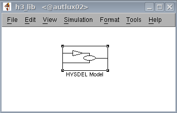 h3_lib.png
By copying this block to your individual scheme you can simulate evolution of the given system. Hysdel3 Simulink block requires the name of the Hysdel file, symbolical parameters (if any), sample time, and initial conditions (if any). If all these fields are filled, input/output ports are automatically generated where boolean ports are red colored.
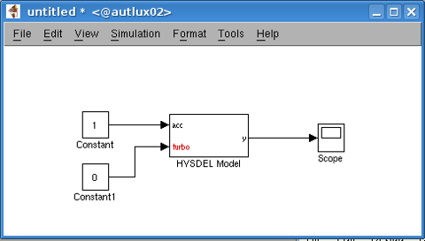 turbo_car.png
Hysdel3 allows automatic creation of master files. In Simulink, this is identical to creating a subsystem which contains only Hysdel3 blocks or other subsystems with Hysdel3 blocks. For instance, if we want to create a master file for two blocks "T1" and "T2" of one Hysdel file "single_tank" with single input and single output. The master block will look like in
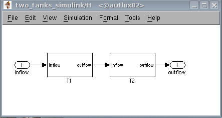 T1T2.png
and it is a subsystem with a name "tt".
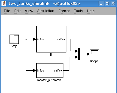 tt.png
By invoking the parser with the name of the given subsystem
>> h3_sim2hys('two_tanks_simulink/tt')
Hysdel3 automatically generates a file "tt.hys" and this file is a master for the block "tt". It is located in the current directory and it can be used as individual Hysdel file.