Laboratory Processes
- Distillation column - Armfield UOP3CC
- Membrane separation plant
- Multifunction station - Armfield PCT40
- Training station - Armfield PCT23
- Three tank system - DTS200
- Heat exchanger - LTR 700
- Ball and plate apparatus
- Magnetic levitation
- Lego Mindstorms
- Hydraulic system - uDAQ28/3H
- Thermo-optical plant - uDAQ28/LT
- Liquid tanks
- Electric actuator
- Rotary inverted pendulum Furuta
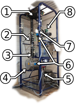
Distillation column - Armfield UOP3CC
Laboratory station Armfield UOP3CC represents the distillation column. It enables the future engineers to test the initial stage in the process engineering, as well as the design and implementation of advanced control strategies using models. The plant allows both continuous and batch operations.
The different possibilities for control loops are:
Controller can be implemented using:
Hardware:
|
Fig. UOP3CC: Distillation column Armfield
|
Membrane separation plant
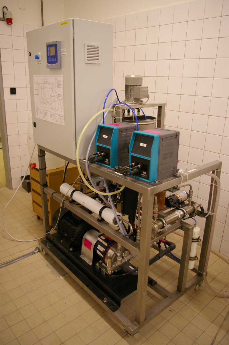
A membrane is a selective barrier; it allows some things to pass through but stops others. These processes have found a wide range of applications. In food industry it is used for fruit juice and milk clarification and temperature plays an important role in this. In pharmaceutical industry the membrane separation processes are used for different aims like albumin production from human blood and anti body preparation. Biotechnological industries use membrane processes for enzyme concentration and the removal of impurities like peptides and salts. In automotive industry they are used in paint and adhesive clarification e.g. Fiat, Ferrari use microfiltration to produce high quality body paints.
The membrane plant shown is used for various types of filtration, such as nanofiltration, ultrafiltration and reverse osmosis. System management is done using industrial control systems, PLC, SCADA, and PC operator station that is used for controlling and collecting data from various sensors (pressure, temperature and conductivity) using Matlab / Simulink. Control allows testing and application of new control algorithms.
Multifunction station - Armfield PCT40
Multifunctional Armfield PCT40 station is a system with multiple devices. It consists of a base module and additional modules, i.e. PCT40, PCT41, and PCT42. PCT40 basic module (FIG. PCT40_1) comprises two chemical processes, i.e. liquid tanks and the heat exchanger. In the basic module are also arranged pipes, pumps, valves, sensors and other electrical components which are used for measurement and control of process variables. The station is connected to the water supply through a pressure regulator with an integrated filter.
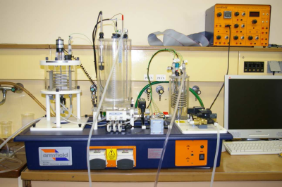
PCT41 plugin is a chemical reactor, which is located on the left side of the basic module. PCT42 an additional module; is a sensor for measuring pH. All three of chemical devices can be joined together. Various types of controllers can be implemented to the individual devices.
Heat exchanger
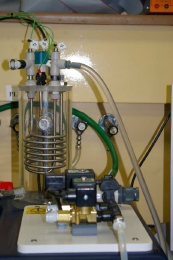
The heat exchanger (Fig. PCT40_2) consists of a cylindrical vessel, which is located in the right part of the basic module PCT40. It contains two coils, one for cooling, and the other for heating. The temperature of the liquid in the cooling coil is sensed at the input and the output. Another temperature sensor senses the temperature of the liquid inside the heat exchanger. The level of liquids is measured in the exchanger. Level sensor ensures that the heating coil will not turn on until it is completely submerged. There is a thermostat which is used for controlling temperature, i.e. if the temperature of the liquid exchanger exceeds the target value, the heater turns off. The liquid in the heat exchanger and the cooling coil may be supplied through the PSV, or by means of a peristaltic pump. For pumping hot liquids; a gear pump is used.
Chemical reactor
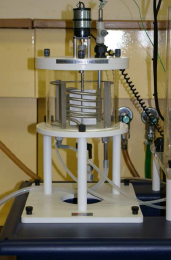
Chemical reactor (Fig. PCT40_3) consists of a cylindrical vessel, which is located on the left side of the basic module PCT40. Heating or cooling of the reactor coil is manageable. The homogeneity of the reaction mixture is ensured by an agitator in the middle of the container. Feeding to the reactor is done using peristaltic pumps or via the PSV. To have a constant water level in the reactor, the reaction mixture is provided with an overflow pipe. The temperature of the inlet can be monitored by a temperature sensor. The concentration of the product is measured by the conductivity sensor. It also posseses a manual drain valve.
Liquid tank system
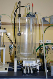
The liquid tank (FIG. PCT40_4) is a cylindrical container made of acryl, which is located at the center of the basic module PCT40. Inside the cartridge is placed a removable cylinder that is used to enlarge the volume. Thus, the boiler itself forms in an annulur space. The liquid is fed into the container from above. It was used as the liquid water to tap water supplied with this medium. The liquid in the reservoir can be introduced through the PSV, or by means of a peristaltic pump. There we have two peristaltic pumps, which are located on the front of the basic module. Inlet water flow is measured by a flow meter F1. Water from the reservoir flows through the solenoid valves SOL2 and SOL3, or is pumped with a peristaltic pump. The liquid outlet is through the manual valve at the bottom of the container. It also contains the overflow pipe, which prevents buffer overflow.
Multifunctional control station - PCT40
Multifunctional PCT40 station can be controlled via USB, I/O card or by PCT43.
Armfield company delivered the complete station with educational software through which we can communicate with the station. To control the station using the software, we need a computer. The computer communicates with the Multifunctional station via USB. The software includes diagrams of chemical processes, allows you to render and keep the values of input and output data. Also user can manage processes with a two position modulating controllers, and branched control circuits. Input to the chemical processes can be set manually. The software is a file that includes several tasks for students on laboratory exercises.
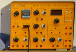
The device PCT43 (Fig. PCT43_1) is used to control the multifunctional station PCT40 without a computer connection. It contains controls for pumps, valves, heating, and PID controller. Process values measured by the sensors are displayed on the right side of the display device. To control the process data one can use PSV, peristaltic pumps, and a pump for the hot liquid, which can be set manually or by using a PID controller. The basic and additional modules are connected to the device via PCT43 technical card.
With multistation one can also communicate through the software MATLAB. To control the multifunctional station MATLAB, Simulink, and Real-Time Toolbox are used. Simulink diagram communicates with the station via the multifunction I/O card MF624 from Humusoft.
Training station - Armfield PCT23
It is used for demostrating various control methods and startegies. The plant can be seen in Fig. PCT23_1. The operation and control of the system is manged using a computer.
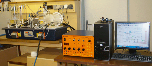
Three tank system - DTS200
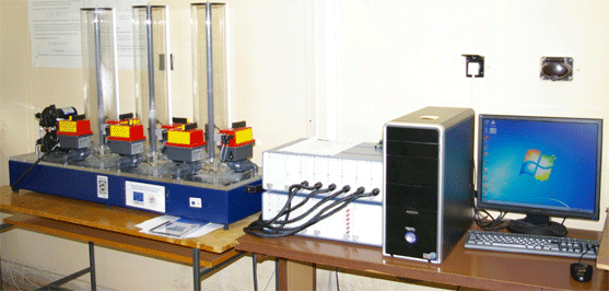
The process shown in Fig. DTS200_1 consists of three identical cylindrical liquid tanks, associated piping, and valves. The water is driven by two pumps and it circulates in a closed loop. More information can be found at manufacturer's website.
Heat exchanger - LTR 700
Heat exchanger LTR 700 (Fig. LTR700_1) is able to ensure the desired air flow rate and a temperature of 25 to 75 °C. It consists of a tube containing a heating coil and a fan with power supply.
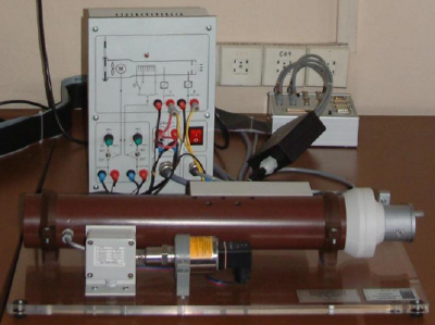
The heat exchanger has two measurable output signals (temperature, air flow rate) as well as two input signals (fan speed, heating).
The following control loops can be implemented over it:
- Simple control loops:
- for controlling flow of air, in case of uncontrolled temperature
- for controlling heating temperature, in case of uncontrolled air flow
- temperature control using fan speed, in case of uncontrolled heating
- Cascade control loops:
- primarily for temperature control; and secondarily controlling the flow rate, by adjusting the heating
- primarily for temperature control; and secondarily controlling the flow rate, by adjusting the fan speed.
Control of the exchanger is done by a computer with a card dSPACE 1102 containing DSP processor from Texas Instruments. Programming is done in Simulink, resulting scheme is automatically recompiled on DSP processor. Visualization is programmed via software Control Desk (dSPACE).
Ball and plate apparatus
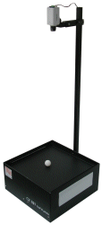
This laboratory model (Fig. CE151) is a two-dimensional system designed for experimenting with unstable dynamical systems using different control algorithms. This dynamic model with two inputs and two outputs can drive two coordinate spheres regardless of their interaction.
The system includes a plate that can be tilted at angles to adjust the position of the ball. This may be at the center of tilting in two directions. Servo system consists of a control card engine, and two motors located under the plate. The sensor system comprises a CCD camera, and it is used to detect the current position of the ball.
Magnetic levitation
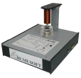
This model (Fig. CE152) is a one-dimensional system with one input and one output. It is a strongly nonlinear dynamic system. It is used for experimenting with different control algorithms.
The model is connected to the PC using an input-output measuring card MF614 (standard measuring card with eight 12-bit A/D converter, 8 digital TTL input (output). Two channels are used to measure the position of a ball and coil current. For the control of the power amplifier an analog output is used.
Ball levitates in a magnetic field coil. To measure the position of the ball a magnetic position sensor is used. Current to the coil is amplified and external amplifier is proportional to the input electrical voltage.
Hydraulic system - uDAQ28/3H
 |
 |
|
Fig. uDAQ28_3H_1: Hydraulic system uDAQ28/3H
|
Fig. uDAQ28_3H_2: Hydraulic system uDAQ28/3H
|
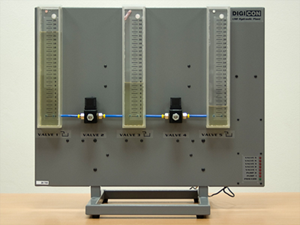
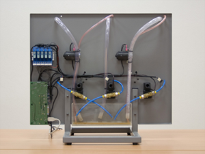
The plant is has two pumps and five solenoid valves, which can be used to create a wide range of tasks for identification and control, and by using remote access via the internet.
At the output/filtred output, the height of the water columns can be measured using three pressure sensors located at the bottom of each tank.
Measurement and communication system uDAQ28 / 3H is used for data transmission and processing, using its own microprocessor. From the user's perspective is the comparison with existing solutions, in this system the additional asset is the communication via the USB interface, which allows you to connect to any PC without the need to purchase and install special input-output cards. To supply safe voltage of 12V and 24V, small adaptors are used (like mobile phone chargers).
More information: hydraulic system uDAQ28/3H
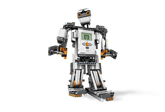
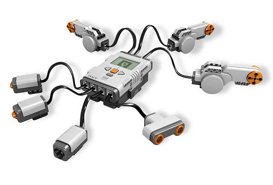
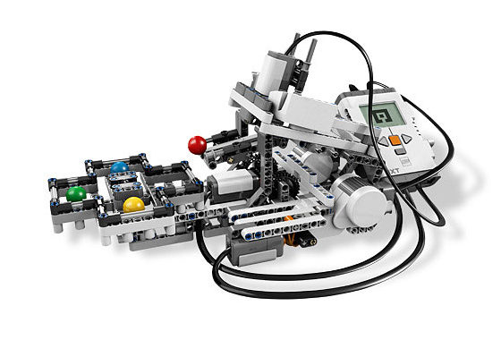
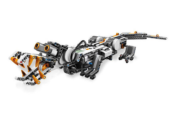
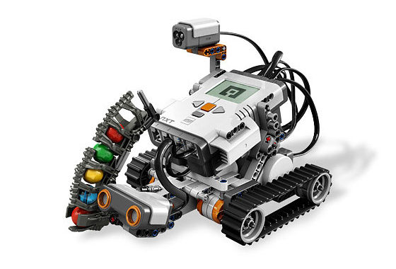
Lego Mindstorms

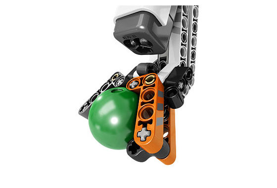
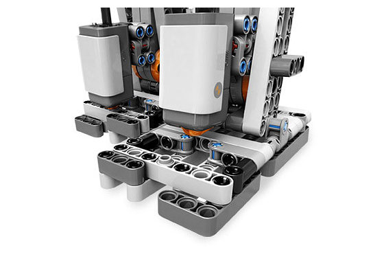
LEGO Mindstorms is a set of programmable robotic kits manufactured by Lego. Mindstorms NXT kit version consists three motors and a sensor for touch, light, sound and distance. It can also have a set up model of a computer-controlled electromechanical parts.
Thermo-optical plant - uDAQ28/LT
 |
 |
|
Fig. uDAQ28_LT_1: Thermo-optical plant uDAQ28/LT
|
Fig. uDAQ28_LT_2: Thermo-optical plant uDAQ28/LT
|
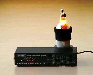
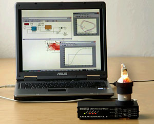
The system has three input quantities - voltage of light bulbs, which represents the heating element and light at the same time, the fan voltage (used to cool the temperature in the system) and voltage of light-emitting diode, which is the second possible source of light optical channel. It is also possible to set a sampling period and time constants of embedded derivative filter.
At the output, 7 variables can be measured: temperature in the heated area (either directly or after pre-filtration), the reference ambient temperature, light intensity (directly or after pre-filtration), speed and current to the fan motor.
Measurement and communication system uDAQ28/LT is used for data transmission and processing, and it uses its own microprocessor. From the user's perspective is the comparison with existing solutions, in this system the additional asset is the communication via the USB interface, which allows you to connect to any PC without the need to purchase and install special input-output cards. To supply safe voltage of 12V small adaptors are used (like mobile phone chargers).
More information: thermo-optical system uDAQ28/LT
Liquid tanks
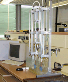
The basic parts are two pairs of superimposed hydraulic tanks in a vertical plane associated to a vessel. The tanks are equel in height, while the internal cross-section of the vessels on the right side is smaller. The two streams of the water from the bottom of the storage tank are pumped to the top of the container, and through the diaphragm it flows to the second vessel below it. From there the water flows back into the lower vessel.
Electric actuator

This actuator (Fig. Servo) allows one to take four parameters: voltage, speed, location, and desired position. The control variable is entering voltage. From the point of view of system, it can be characterized as a servo drive system comprising an integrator, and this means that the system is on the border of stability. There appears to be a phenomenon of hysteresis, combined resistance of the environment at the start of the actuator. Responses of individual quantities to the input voltage are quick, operation of the actuator is simple and secure. The actuator is connected to a current amplifier, signal converters, and the PC from which the user can control the actuator.
The drive is currently controlled by dSPACE systems, just like the heat exchanger LTR 700
Rotary inverted pendulum Furuta

Rotary inverted pendulum FPM-211 is composed of the following: an arm rotating in the horizontal plane where one of its ends is mounted on a motor shaft and where a rod is mounted on its other end. The rod's lower end is mounted on the arm's free end in such a manner that, the rod is moving as an inverted pendulum in a plane that is at all times perpendicular to the rotating arm. Mathematical model of this system is characteristic by its nonlinearity and fast dynamics. Objectives for control algorithms are either stabilization at upright/downright position or Swing up. They can be applied directly in REX environment as block scheme or script written in C.


